 explained
the modifications to me and I've included his comments below which explain
them fairly well.
explained
the modifications to me and I've included his comments below which explain
them fairly well.
Gary Slagel
NØSXX
Andy Palm, N1KSN, came across the directions for the Mountain Topper and
built his version of the MT-2. He built it very much the same as my
original but added a few modifications of his own. When I asked, he
graciously sent me the following excellent photos. During the course
of exchanging a few emails Andy
explained
the modifications to me and I've included his comments below which explain
them fairly well.
MOD 1:The Radio Shack whip would not fit inside the 5/16" tube, so I built a short section of 11/32" tube with the antenna inserted in the top and a 5/16" section in the bottom. There is some thin brass shim stock wrapped on the whip at the top of the tube to make it a bit more stable.
MOD 2:On the base I decided to install a BNC connector, similar to how it is done on the PAC-12. I used a scrap piece of PCB held to the dowel with the ground radial screw for the mount.
MOD 3:I also added two spade male connectors to this screw for my radial connections (my current station standard for connecting radials), but I might still go with the alligator clips.
MOD 4:Rather than using electrical tape on the coils, I'm trying the use of two cable ties to hold the coil in place.
MOD 5:I'm going to try a 20 foot cable of RG-174 with a toroidal RF choke at the antenna end.
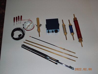
PICTURES: I took a front and back view of the base piece, showing the male quick disconnects attached to the ground screw using ring terminals, and my BNC connector and RF feedline choke. I also took a picture of the 20m coil which shows how I attached the whip using a 11/32" tube section with the usual 5/16" tube ferrule. The fourth picture is of the music stand. It fits in a 7/16" hole in the base and is the Hamilton 400-N model.
Note 1:I bought a brand new Hamilton 400-N music stand for the base ($18) and cut an additional hole to allow the legs to remain wider (as you did).
Note 2:As you mention in your construction instructions, the Achilles Heel of the design is the electrical contact between the #6 screws at the ends of thecoils (and the one end of the base) and the brass tubing. I used an analog VOM on the lowest resistance range to check the continuity and found that I had to very carefully determine just where to set the screw tightness.
Note 3:I built coils for 20m and 15m, adding an extra turn to each, as you suggest. With 26 turns on the coil (the one extra you suggested), I got a minimum SWR of 1:1.4 or so at 14.060 with the top section of the whip reduced to 6" long.
Note 4:My radials are made from unzipped 24 ga. ribbon wire. I got a 100 foot roll of it for $10 from All Electronics. I liked your idea of using grommets for insulators, and I used solid 26 ga. wire at the ends of the radials. For storage I wind the radials on a spool from fly line backing. I decided to use just one set of four radials (ones cut a quarter wavelength for 20m), as they are too close to the ground to be considered elevated. However, I still keep them off the ground to try and get a consistent SWR from one location to the next.
Note 5:I found all the materials (except for the Hamilton 400-N music stand) at the hardware store.
Note 6:I've attached a picture of my setup so far, including my new 40m coil. I could get a minimum SWR of about 1.9:1 with the 40 meter coil and the 20m radials using my Autek analyzer...The 40m coil is wound on a larger wooden dowel of true diameter 1 5/16" (33 mm) and has 65-66 turns. If I had it to do over again, I'd use 67 turns just in case, as the resonance point with full whip extension is just a smidgeon under 7.000 MHz. With the radials reasonably taut, I had no physcial stability problems, but my backyard is pretty level.
Note 7:I think the quantities should be reversed for the two sizes of tube. Two of the 11/32" tubes are needed (not one) while one 5/16" tube is what is needed for the joints.
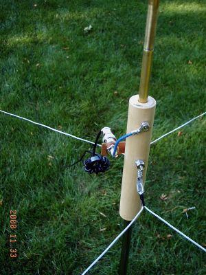 Back
view of the base showing quick disconnect radial connector
Back
view of the base showing quick disconnect radial connector
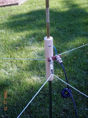 Front
view of the base showing the bnc connector assemble
Front
view of the base showing the bnc connector assemble
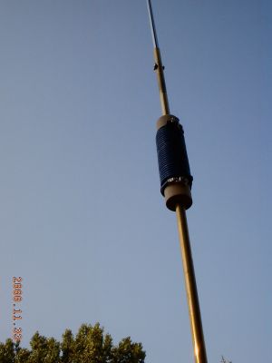 20
Meter Coil
20
Meter Coil
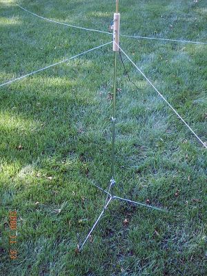 MT-2
on the music stand ready for action!
MT-2
on the music stand ready for action!